Technical Transformation of Inlet Blowing Beer Filling Machines
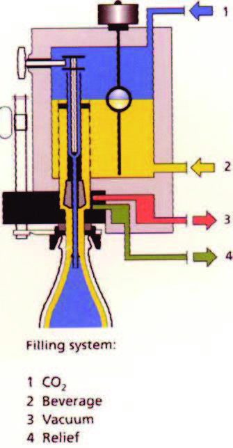
The beer filling machine is the core equipment of the filling line. The quantity and quality of products are closely related to the working state of the wine machine, and it is also the most complicated part that needs to be controlled, adjusted and operated in the filling production process. The wine filling machine is developed around the filling process. The principle of isobaric filling is as follows: the bottle is fed into the bottle feeding screw of the filling machine by the bottle feeding belt, and then sent to the bottle supporting cylinder of the rotary table at a certain distance by the bottle feeding star wheel, and then raised. Under the guidance of the centering device, the bottle mouth presses the blanking opening of the filling valve tightly to form a seal. After the bottle is vacuumed, the back pressure gas (CO2) in the liquid storage tank is flushed into the bottle. When the pressure of the gas in the bottle is equal to that in the liquid storage tank, the liquid valve is opened under the action of the spring. At this time, the beer is automatically poured into the glass bottle along the wall of the bottle through the guiding function of the umbrella-shaped reflecting ring on the air return pipe. The CO2 in the glass bottle is replaced back into the liquid storage tank through the air return pipe. When the liquor rises to a certain height and the air return pipe is closed, the drinking will be stopped automatically. Then, the liquid valve and air valve are closed, and the pressure gas at the bottleneck is discharged to prevent the gassy liquor from gushing when the glass bottle falls, thus completing the whole filling process.
Existing problem
The filling machine in our factory adopts a mechanical wine valve for equal pressure filling. Its wine filling principle is divided into six stations as shown in Figure 1. Including 1) pre-vacuuming (orange). 2)CO2 washing (blue). 3) Vacuum again (orange). 4)CO2 standby pressure (blue). 5) Wine filling process (yellow). 6) Pressure relief (dark green).

The designed production capacity of this distiller is 36,000 bottles/hour. After 10 years of operation, all the performance indexes have declined, which can't reach the original designed production capacity. In particular, the secondary liquor rate of the produced products increases month by month, and the dissolved oxygen is often unqualified. As can be seen from Figure 1.2, the dissolved oxygen value in the bottle increased month by month in the months after the annual maintenance of the wine machine over the years, which seriously affected the flavor value and brand image of the product. After inspection, it is found that there are independent devices in the structure of the wine valve, such as a CO2 pipe, vacuum pipe and pressure relief exhaust pipe, while the residual foam is left in the inner cavity. After a period of isobaric filling, the residual foam will remain in the inner cavity, resulting in the insufficiency of the next six filling stations, which will further affect the qualified rate of dissolved oxygen and the inferior liquor rate of the product.
Transformation method
In order to improve the qualified rate of dissolved oxygen and reduce the inferior liquor rate of products, a set of blowing devices must be designed to solve this technical problem. As shown in Figure 2.1, the blowing device is installed between the outlet and the inlet of the wine filling machine, and its function is to clean up the residual foam in the cavity, so that the wine filling valve can circularly fill wine in a good environment, thus improving the production efficiency of the wine filling machine.

Figure 2 Appearance diagram of blowing device
The blowing device comprises two parts: an automatic valve opening part and a forced valve closing part. Fig. 2.2 is the structure diagram of the automatic valve opening component. By modifying the electrical program of PLC, the cylinder action of the automatic valve opening component and the entrance induction valve opening and wine filling action can be started synchronously. When the bottle is filled with wine, the cylinder moves, the wine valve is lifted and opened, CO2 is quickly discharged due to the pressure difference, and the residual foam in the cavity is blown clean; when there is no bottle filled with wine, the cylinder does not move, and the wine valve remains closed, thus reducing the loss of CO2. The automatic valve opening part adopts a separate bracket, which is composed of two bottom plates with four M10 slots. It can be adjusted flexibly, and the height can be adjusted to the best position according to the wear of 108 wine-filling valves in different states. The right-angle bottom plate is equipped with a double-acting cylinder with a fork, the direction of its action is controlled by an electromagnetic valve, and it is controlled by a PLC program to always keep the height of the wine filling action with the wine valve.
Consistent.
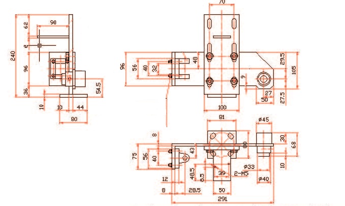
Fig. 3 is the structure diagram of the forced valve closing part, which keeps a distance of about 3 stations from the automatic valve opening part. When the residual foam in the cavity is completely blown clean, the valve must be forced to close after passing through here, so as to ensure that the cavity of the wine valve is closed when the wine filling machine runs to the entrance, and the isobaric filling in the next cycle can be effectively carried out.
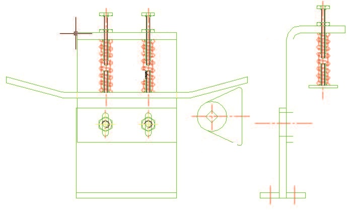
The automatic valve closing component adopts a separate bracket, which is composed of two stainless steel plates with two M10 slots. It can be adjusted flexibly, and its height can be adjusted to the best position according to the site conditions. The bending plate is equipped with two adjusting screws equipped with compression springs. After the adjusting screws are placed in proper positions, the spring device is used to automatically adjust the balance, automatically absorb the shock, and finally automatically compensate for the gap of the position error of each wine valve. Because the stability of the fixing ring of the filling machine is not high, and the control mechanism of the wine valve is easy to wear and become loose, the wine valve cannot be closed well. Using the stainless steel guide plate to slowly close the wine valve switch can improve the stability of the whole device and achieve accurate control of the filling valve.
Modified effect
From the feedback effect, as shown in Figure 3.1, the qualified rate of dissolved oxygen is significantly improved. This design completely meets the design requirements, which not only improves the product quality but also improves the image of the product, greatly reduces the number of short wines and improves the qualified rate of filling. At present, there are two wine filling machines modified by our company, which can save tens of thousands of yuan of liquor cost every year by reducing the liquor rate by 0.5%. By reducing the frequency of failures and shortening the maintenance period of spare parts, the annual spare parts cost can be saved, and the economic benefits generated by reducing the failure rate of equipment are considerable. Many peer manufacturers have the same type of equipment, which can be popularized and applied to the industry.
Figure 3.1 Data Table of Dissolved Oxygen Results
Existing problem
The filling machine in our factory adopts a mechanical wine valve for equal pressure filling. Its wine filling principle is divided into six stations as shown in Figure 1. Including 1) pre-vacuuming (orange). 2)CO2 washing (blue). 3) Vacuum again (orange). 4)CO2 standby pressure (blue). 5) Wine filling process (yellow). 6) Pressure relief (dark green).
The designed production capacity of this distiller is 36,000 bottles/hour. After 10 years of operation, all the performance indexes have declined, which can't reach the original designed production capacity. In particular, the secondary liquor rate of the produced products increases month by month, and the dissolved oxygen is often unqualified. As can be seen from Figure 1.2, the dissolved oxygen value in the bottle increased month by month in the months after the annual maintenance of the wine machine over the years, which seriously affected the flavor value and brand image of the product. After inspection, it is found that there are independent devices in the structure of the wine valve, such as a CO2 pipe, vacuum pipe and pressure relief exhaust pipe, while the residual foam is left in the inner cavity. After a period of isobaric filling, the residual foam will remain in the inner cavity, resulting in the insufficiency of the next six filling stations, which will further affect the qualified rate of dissolved oxygen and the inferior liquor rate of the product.
Transformation method
In order to improve the qualified rate of dissolved oxygen and reduce the inferior liquor rate of products, a set of blowing devices must be designed to solve this technical problem. As shown in Figure 2.1, the blowing device is installed between the outlet and the inlet of the wine filling machine, and its function is to clean up the residual foam in the cavity, so that the wine filling valve can circularly fill wine in a good environment, thus improving the production efficiency of the wine filling machine.
Figure 2 Appearance diagram of blowing device
The blowing device comprises two parts: an automatic valve opening part and a forced valve closing part. Fig. 2.2 is the structure diagram of the automatic valve opening component. By modifying the electrical program of PLC, the cylinder action of the automatic valve opening component and the entrance induction valve opening and wine filling action can be started synchronously. When the bottle is filled with wine, the cylinder moves, the wine valve is lifted and opened, CO2 is quickly discharged due to the pressure difference, and the residual foam in the cavity is blown clean; when there is no bottle filled with wine, the cylinder does not move, and the wine valve remains closed, thus reducing the loss of CO2. The automatic valve opening part adopts a separate bracket, which is composed of two bottom plates with four M10 slots. It can be adjusted flexibly, and the height can be adjusted to the best position according to the wear of 108 wine-filling valves in different states. The right-angle bottom plate is equipped with a double-acting cylinder with a fork, the direction of its action is controlled by an electromagnetic valve, and it is controlled by a PLC program to always keep the height of the wine filling action with the wine valve.
Consistent.
Fig. 3 is the structure diagram of the forced valve closing part, which keeps a distance of about 3 stations from the automatic valve opening part. When the residual foam in the cavity is completely blown clean, the valve must be forced to close after passing through here, so as to ensure that the cavity of the wine valve is closed when the wine filling machine runs to the entrance, and the isobaric filling in the next cycle can be effectively carried out.
The automatic valve closing component adopts a separate bracket, which is composed of two stainless steel plates with two M10 slots. It can be adjusted flexibly, and its height can be adjusted to the best position according to the site conditions. The bending plate is equipped with two adjusting screws equipped with compression springs. After the adjusting screws are placed in proper positions, the spring device is used to automatically adjust the balance, automatically absorb the shock, and finally automatically compensate for the gap of the position error of each wine valve. Because the stability of the fixing ring of the filling machine is not high, and the control mechanism of the wine valve is easy to wear and become loose, the wine valve cannot be closed well. Using the stainless steel guide plate to slowly close the wine valve switch can improve the stability of the whole device and achieve accurate control of the filling valve.
Modified effect
From the feedback effect, as shown in Figure 3.1, the qualified rate of dissolved oxygen is significantly improved. This design completely meets the design requirements, which not only improves the product quality but also improves the image of the product, greatly reduces the number of short wines and improves the qualified rate of filling. At present, there are two wine filling machines modified by our company, which can save tens of thousands of yuan of liquor cost every year by reducing the liquor rate by 0.5%. By reducing the frequency of failures and shortening the maintenance period of spare parts, the annual spare parts cost can be saved, and the economic benefits generated by reducing the failure rate of equipment are considerable. Many peer manufacturers have the same type of equipment, which can be popularized and applied to the industry.
| Sampling time | bright beer tank (ug/L) | Average dissolved oxygen in draft beer (ug/L) |
| 20200816 | 81 | 100 |
| 20200817 | 82 | 90 |
| 20200822 | 80 | 88 |
| 20200911 | 78 | 84 |
| 20200924 | 62 | 62 |
| 20201008 | 70 | 71 |
| 20201019 | 65 | 60 |
Figure 3.1 Data Table of Dissolved Oxygen Results
